Parametric Frigate Hull Form Sizing and Optimisation
By T. Noyan Kılınç – The Parametric Hull Form Optimization Model, detailed in this paper, was developed for modern frigate-type hull forms.

Brief Description Of The Model
The Parametric Hull Form Optimization Model, explained in this paper, has been developed for “frigate type hull forms”.
The Model runs according to the following principles:
- The displacement is fixed,
- The hull form is characterized by certain parameters,
- These parameters are selected also as inputs to applicable resistance estimation, seakeeping performance assessment and stability performance assessment techniques,
- Parameters are grouped into “independent parameters” and “dependent parameters”,
- Independent parameters are assigned by numerical values from an associated set of values that represent trends for frigate type hull forms for that parameter,
- Dependent parameters are calculated acording to the values assigned to the independent parameters,
- When a random combination of numerical values are assigned to independent variables from their associated set of values, a “probable hull form geometry solution” is obtained,
- There are criteria defined for preserving geometrical relationships, maximum allowed machinery power, minimum acceptable seakeeping performance and minimum acceptable stability performance,
- As a new probable hull form geometry solution is obtained at the beginning of each run, certain calculations are then performed to check for appropriate geometrical relationships, acceptable required machinery power, seakeeping and stability performance as per determined criteria,
- If a new probable hull form geometry cannot meet the determined criteria, then it is eliminated,
- The “possible design solutions space” is then downsized into an “acceptable solutions space”,
- At the end, certain techniques are applied to select the “optimum solution” among the “acceptable solutions”.
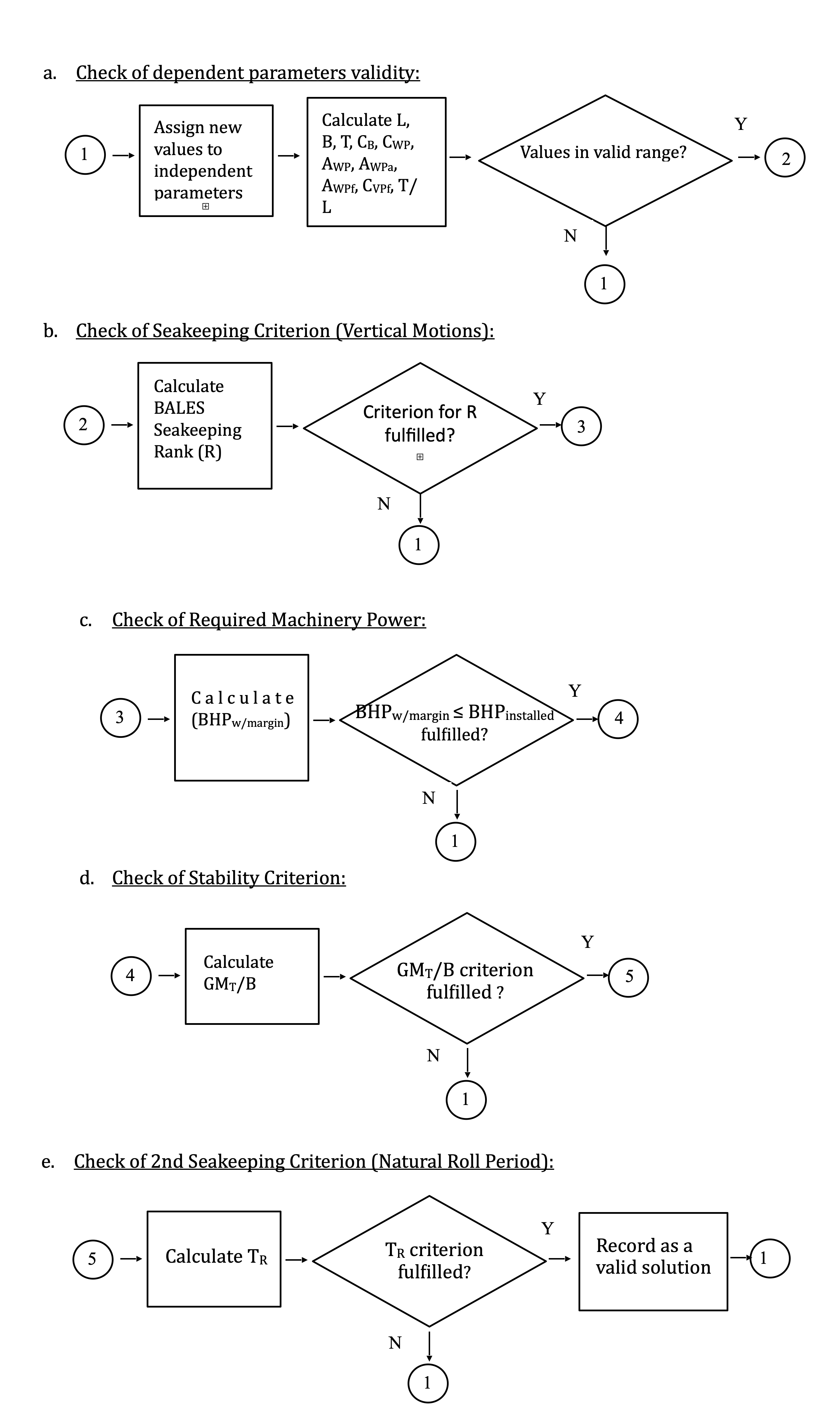
In the following page, a flow chart depiction is given.
Model Flow Chart
Selection Of The Optimum Solution
When the “acceptable solutions” are obtained, various assessments are executed by analysing associated data. Plots are helpful in understanding the trends in the results.
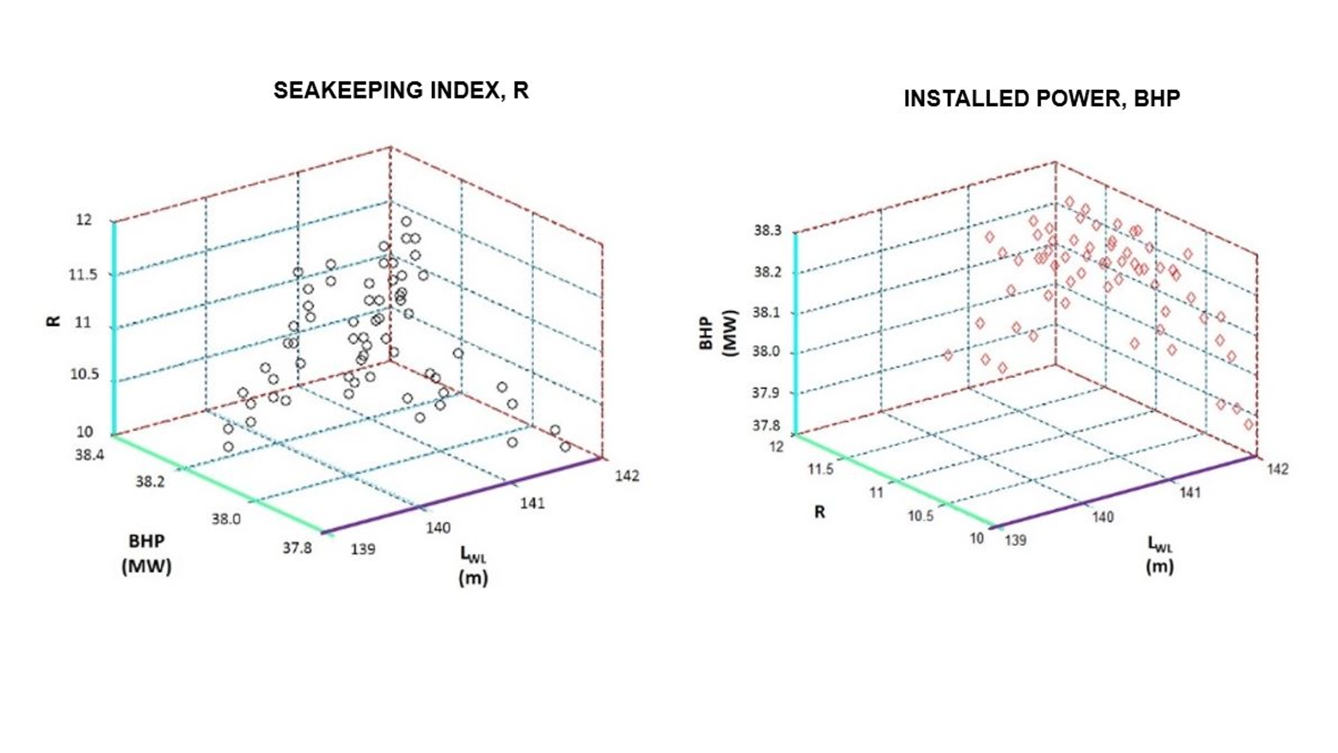
Plots to determine “Non-dominated (Pareto) Frontier” are especially helpful to downsize the candidates, among which the optimum solution is to be selected.
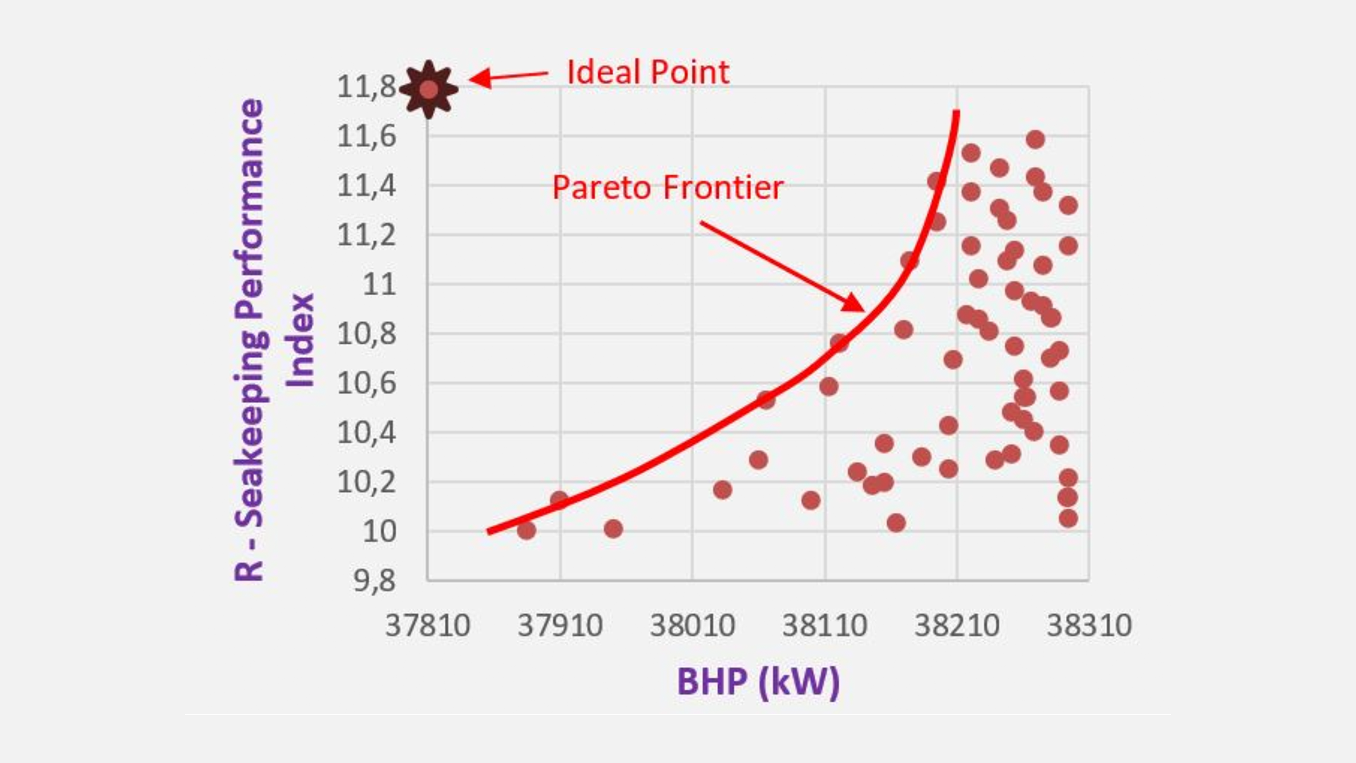
In above example, acceptable solutions are plotted according to their “Seakeeping Index, R” versus “(Required) Installed Power, BHP” values. Ideally, a solution which has the highest R and the lowest required installed power is desired. So, this desire determines the “Ideal Point” in the graph. The solutions shown on the “Pareto Frontier” dominates other solutions that are farther to the ideal point. This way, they can be eliminated. The “non-dominated” solutions are then subject to “Expert Selection” technique to determine the “Optimum Solution” to start to design.
An example frigate hull form, which was determined according to this method, is shown below: